
50 kW
Maximum Capacity:
800 kW
Typical Performance Profile
| Model Range | Engine Power | Charge Air Flow | Heat Rejection | Water Flow | Dry Weight |
|---|---|---|---|---|---|
| EC140 Series | 50 kW | 2.5 kg/min | 6.5 kW | 30 l/min | 5.0 kg |
| FC100 Series | 90 kW | 4.3 kg/min | 9.2 kW | 50 l/min | 6.7 kg |
| FG100 Series | 190 kW | 9.8 kg/min | 20.6 kW | 80 l/min | 10.0 kg |
| GL140 Series | 300 kW | 15.4 kg/min | 34.2 kW | 140 l/min | 17.0 kg |
| GK190 Series | 350 kW | 20.3 kg/min | 48.1 kW | 180 l/min | 36.0 kg |
| JK190 Series | 600 kW | 30.1 kg/min | 71.8 kW | 270 l/min | 53.0 kg |
| PK250 Series | 800 kW | 40.3 kg/min | 99.2 kW | 400 l/min | 97.0 kg |
Operational Thresholds & Limits
| Max Air Inlet Temperature | 250°C (For higher temperatures please contact sales department) |
| Max Air Inlet Pressure (EC120 to GK190) | 5.5 bar g |
| Max Air Inlet Pressure (JK190 and PK250) | 4.0 bar g |
| Baseline Conditions | Performance figures based on air inlet at 180°C at 1.75 bar g and cooling water at 30°C |
Engine Performance Optimization
By dropping the temperature of the compressed combustion air from the turbocharger, incoming air becomes significantly denser. This increases the total air mass supplied to the engine, enabling better combustion efficiency, improved power output, and reduced fuel consumption and emissions.
High-Efficiency Counter-Flow Design
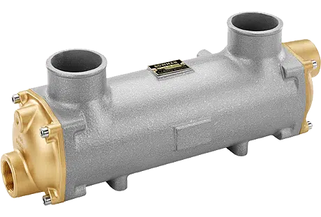
Based on a renowned liquid-cooled shell and tube configuration, these units deliver exceptionally high levels of thermal transfer efficiency. To maintain maximum performance limits, the units must always be piped to run in a counter-flow alignment where air and water pass in opposing directions.
Simplified Serviceability
Routine system maintenance and seasonal cleaning are completely straightforward. By simply unscrewing the end cover retaining screws, the entire internal tube stack easily slides out from the main outer shell body.
Core Exchanger System
- Heavy-duty liquid-cooled shell and tube outer body housing assembly
- High-efficiency internal tube stack configuration
End Cover Configuration
- Standard cast iron end covers (suitable for fresh water/standard closed-circuit loops)
Installation Connections
- Dedicated dual drain port plugs for easy system drainage and maintenance servicing
Aggressive Water Upgrades
- Premium Naval Brass end covers (engineered for high-flow or demanding marine cooling mediums)
- Titanium tube stacks providing a full 10-year guarantee against aggressive chemical attack, salt water, and galvanic reaction
Flow Variations
- Single pass and two-pass configurations to match specific flow requirements